Our second tutorial will focus on simulating an ideal op-amp, using the LTspice simulation tool.
But what is an ideal op-amp?
The figure below shows an ideal op-amp, the input impedance is denoted, as Rin and does not allow any current to flow into it. Ideally, the op-amp input impedance must be infinite, and the output impedance of op-amp denoted as Ro.
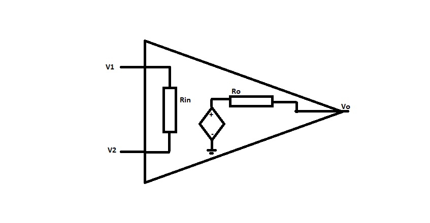
The Ro ensures that the output voltage of the op-amp remains the same for any value of load resistance connected. Ideally, the output impedance of op-amp must be zero. When we look into the open-loop voltage gain of an ideal op-amp, it is infinite. Then the difference between the two inputs can be applied by an ideal op-amp to infinity.
For an ideal op-amp, there is zero output voltage for zero input voltage then the input offset voltage is zero. An op-amp that starts to work as an amplifier at a particular frequency range is known as bandwidth. The bandwidth of an ideal op-amp is infinite, and it can amplify both DC and AC signals. The output voltage of op-amp changes immediately, with a change in the input voltage. If the output voltage doesn’t change immediately with the change in input, then there exists distortion in the output of the op-amp.
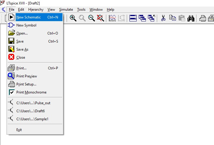
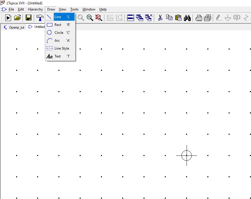
Go to File, click on New Schematic.
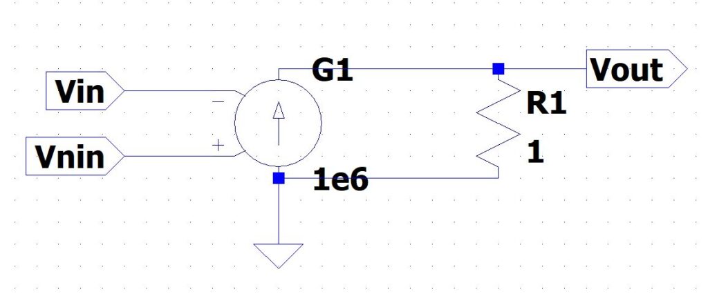
In this example, we will simulate our ideal op-amp using a voltage-controlled current source.
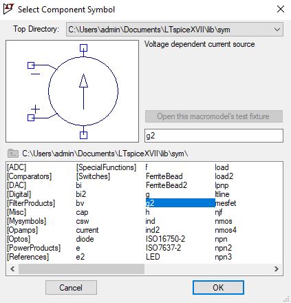
Click on the component icon and select the voltage-dependent current source.
![]()
The inverting input at the top and the non-inverting input at the bottom, in our voltage-dependent current source, and press escape to come out of placing node.
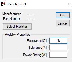
Right-click on the voltage-controlled current source and enter the value of gain as 1e6. Next, click on the resistor and place it on the schematic, change the value of the resistor to 1 ohm, and select the ground symbol and place it on the schematic window.
Connect the voltage-dependent current source and resistor through the wire, select the wire icon, and complete the wiring.
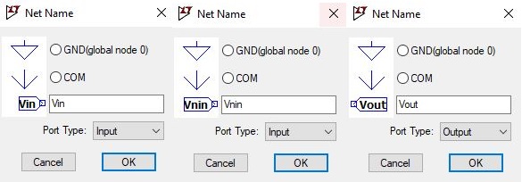
In this example, we must define the port type as an input or output.
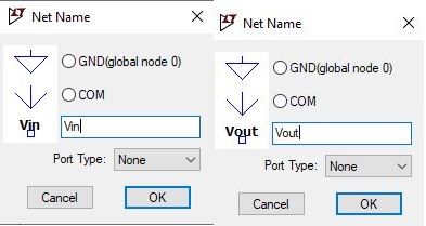
Label the input as Vin placed at inverting input and then Vnin at the non-inverting input.
The output terminal positioned at the resistor R1, click the wire and connect the output terminal with the node of resistor R1. Click on Netname and define the label as Vout and select the port type as output. Save the schematic, click on the file and select save as in this example saved as Opamptut.
The difference across the input terminal across the voltage-controlled current source will generate a current that causes the output to flow through the 1-ohm resistor.
In this example, we will convert this circuit into a symbol.
How to create a symbol in LTspice?
The next section will guide you on how to create a symbol in LTspice.
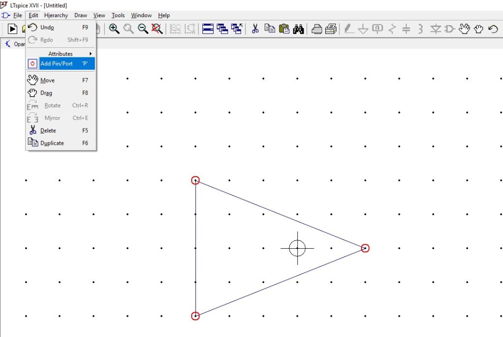
Click on Hierarchy and then select create a new symbol you will get a new schematic.
Save the symbol as Opamptut, this symbol will correspond to the schematic which we had done earlier.
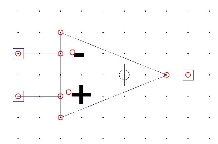
Now click on the draw and then click on Line. We will draw the Op-amp symbol and add the input and output pin to our symbol.
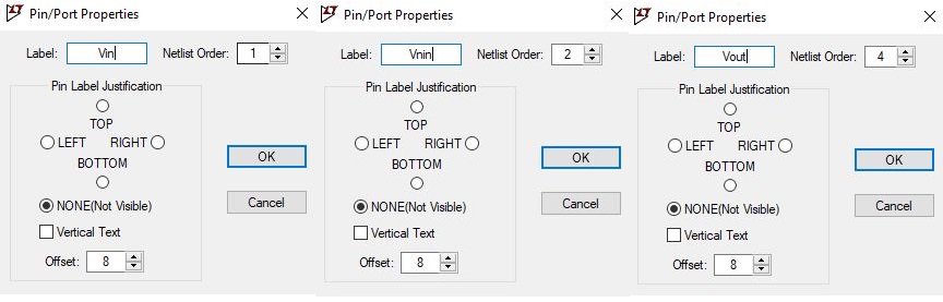
Click on the edit and select add pin/port. Name the pin as, Vin for inverting input terminal and Vnin for non-inverting input terminal, and the output pin as Vout.
Verify the pin table for our circuit, click on view and select pin table. Connect the pins to the Op-amp symbol through drawing lines, which corresponds to the schematic.
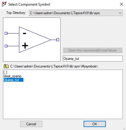
Next, we simulate the Inverting configuration of an Op-amp. Open a new schematic. Use the symbol which we had created previously by selecting the component. Select the directory location, in this example, the symbol name is Opamp_tut, select and click OK and drop the symbol on the schematic.
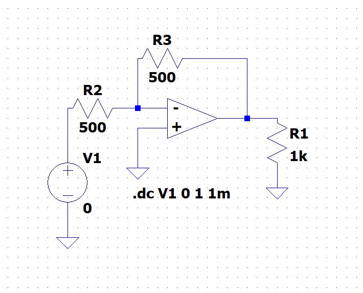
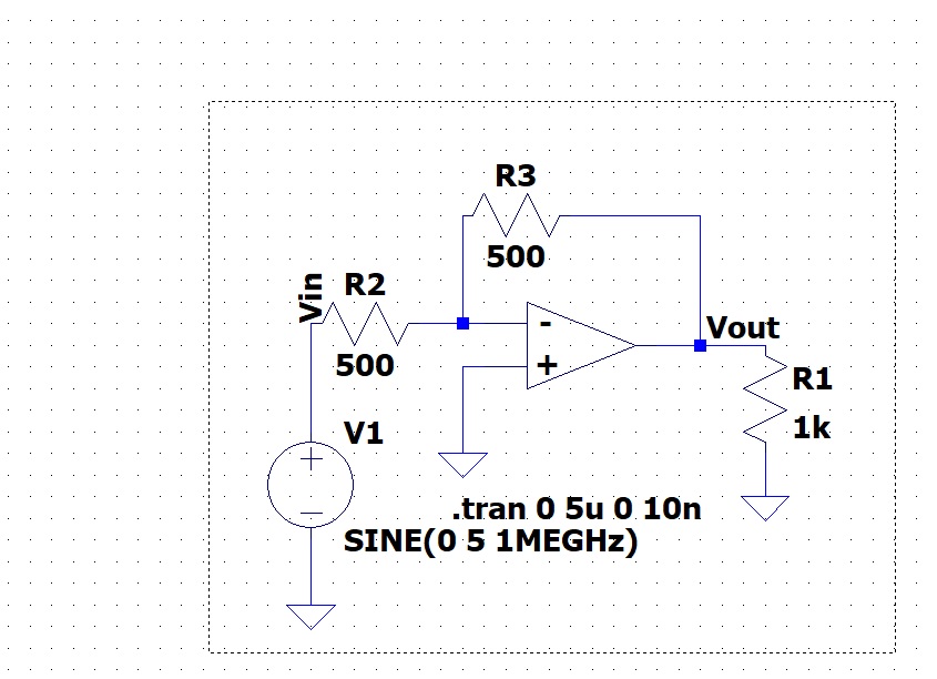
Add a resistor R1 to the schematic, this resistor act as a load and ground the non-inverting terminal input and the voltage source to the inverting input. Also, add resistor R2 and R3, as shown in fig below.
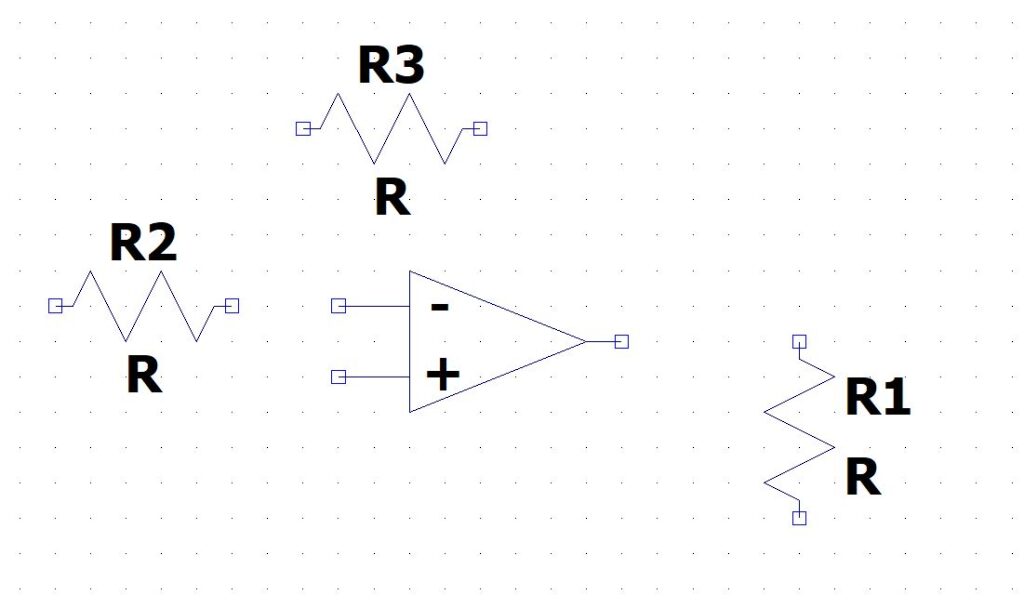
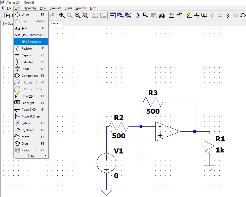
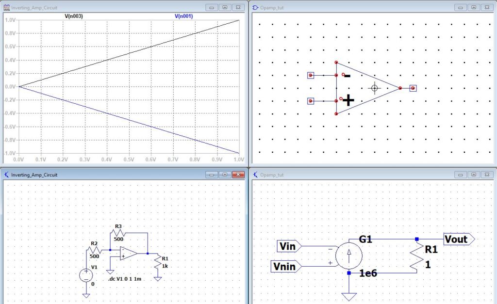
Let us change the value of the resistance value of R2 to 500 ohms and R3 to 500 ohms. Let us do the SPICE analysis and plot the DC sweep.
Let us do the SPICE analysis and plot the DC sweep.
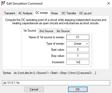
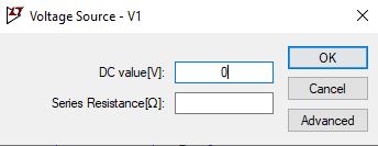
The first source of sweep will be V1, the start value to be 0, and stop value as 1 with 1mv increment. Let us place the SPICE analysis on the schematic and run the simulation.
Click on to the node between V1 and R2 the input of the inverting terminal and the output terminal. The figure below shows the DC sweep.
Now let us make a few changes to our voltage source, right-click on voltage, and click on advanced.
Select SINE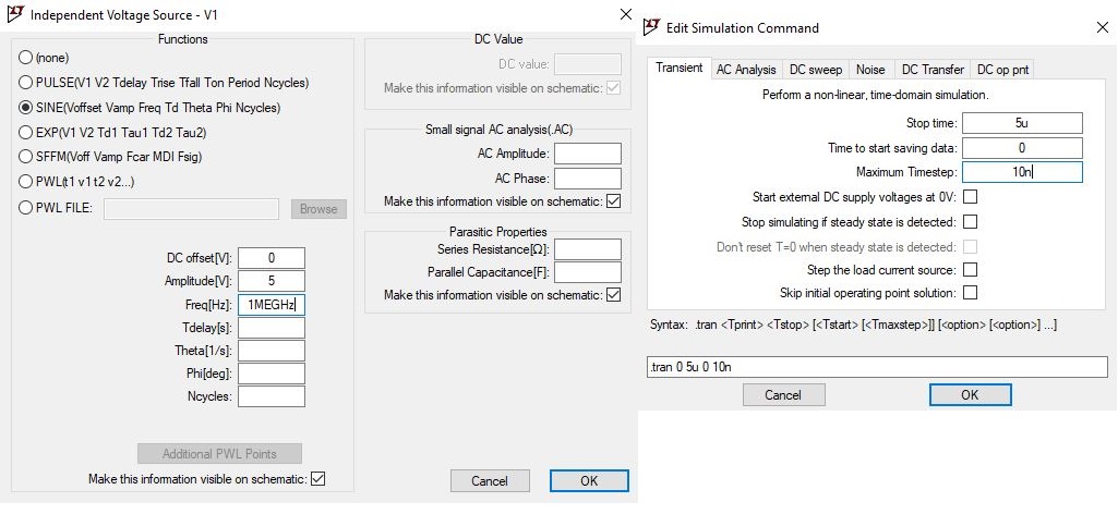
Right-click on to the .dc and change from DC sweep to transient analysis.
Define the stop time as 5us, time to start saving data 0, and maximum time stop 10ns. Label the input as Vin, and Output as Vout.
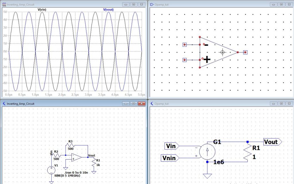
Run the simulation.
When we move the cursor on the circuit in the schematic, select the node on the inverting input and the output. We get the inverted output plot.
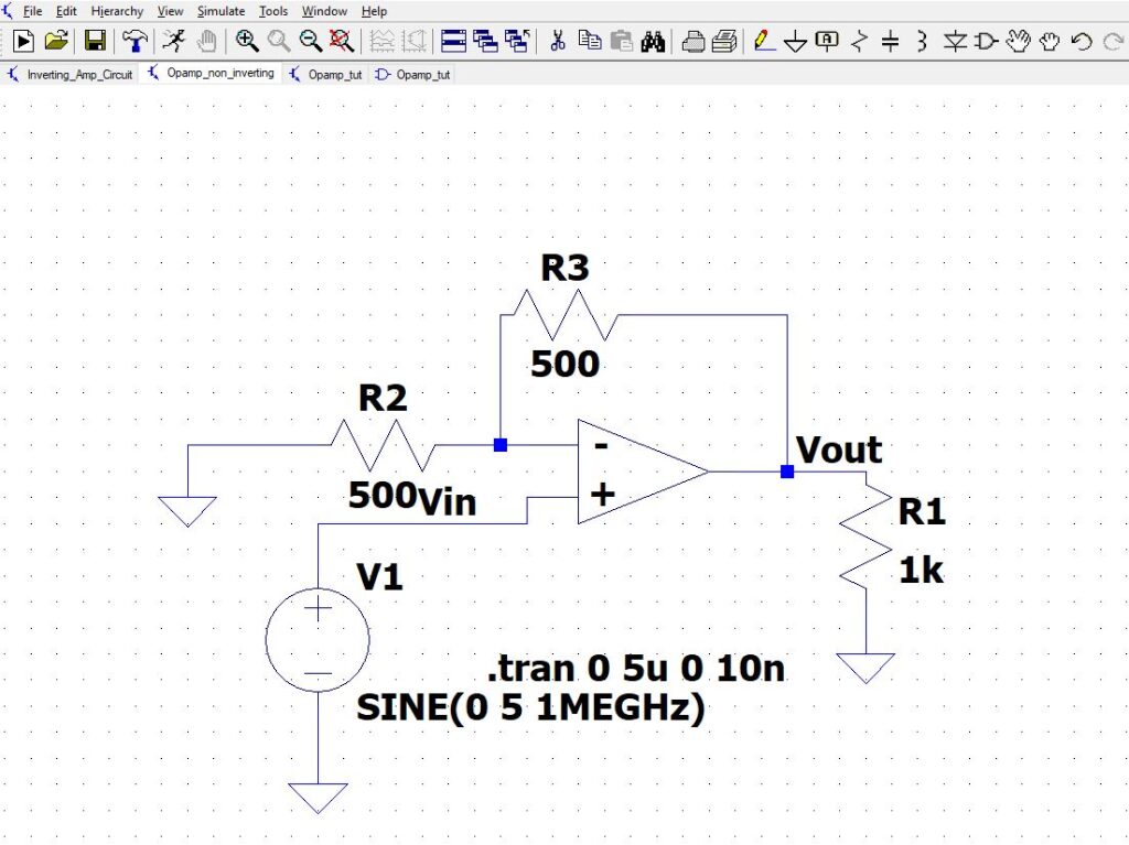
LTspice also gives us the option of copying the entire circuit. For example, we need a non-inverting circuit. Click on a new schematic, go back to inverting circuit schematic and click on the Copy icon and left-click and drag until you cover the entire circuit.
![]()
Save the schematic as a non-inverting circuit.
Now we must make a few changes in your circuit, we will place the input voltage to the non-inverting input.
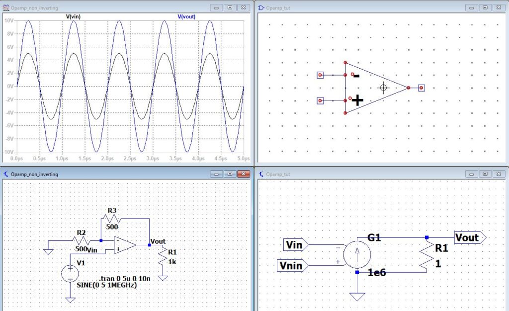
Run the simulation.
The gain output is twice the input because the gain is 1+R3/R2, as shown in the simulated waveform. To distinguish between the Vin, and Vout we can label those using the label net.
End of tutorial.
1 thought on “Simulation of Ideal Operational Amplifier using LTspice.”