Any circuit design engineer before developing a circuit would like to simulate that circuit to understand whether it satisfies the design rules, and this also gives an option of plug, and play which is not possible practically.
To design and develop a circuit with no parts cost and circuit can be evaluated without any physical equipment. Thanks to the SPICE program.
But what is this SPICE program?
SPICE stands for Simulation Program Integrated Circuit Emphasis originally developed at the University of California.
LTspice is a powerful and easy to use schematic capture program and SPICE engine.LT Spice widely used circuit simulator for simulation of several Analog Device amplifiers and regulators. Using LTspice general circuit simulation can also be performed.
How to work with LTspice?
Download the LTspice software from given link below.
https://www.analog.com/en/design-center/design-tools-and-calculators/ltspice-simulator.html#
In this example, we will simulate a simple voltage divider circuit.
Open LTspiceXVII, to open a new schematic editor. Go to File, click on New schematic.
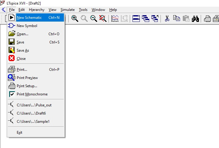
Figure 1: New Schematic
In case if you want to have a grid in the background, click on view and then click on the show grid. We can also use the shortcut for the same Ctrl+G.
In case if you want to have a grid in the background, click on view and then click on the show grid. We can also use the shortcut for the same Ctrl+G.
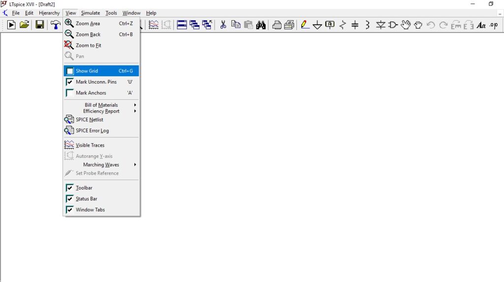
Figure 2: Show Grid
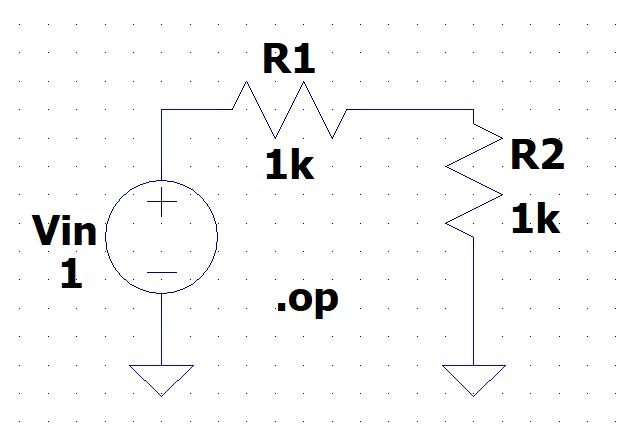
Let us create a simple voltage divider circuit and determine the V operating point. Components required to design a voltage divider circuit are resistor, voltage source, wire, and ground. Click on the resistor symbol, and drag, and drop the symbol on the schematic window. Once the resistor component placed on the schematic editor press escape to get out of the placing node, if we want to move the resistor in our schematic window then, click on the move icon.![]()
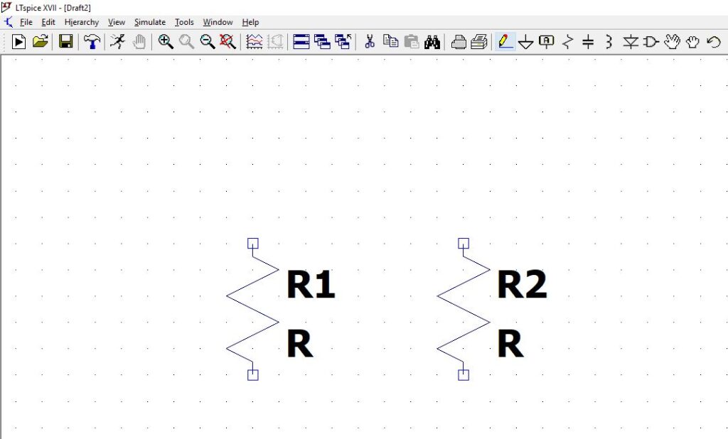
Figure 3: Resistor in LTspice
Select the resistor which you would like to move, if you would like to rotate any of the components in your schematic, then click on edit and select rotate function. You can also use the shortcut Ctrl+R.
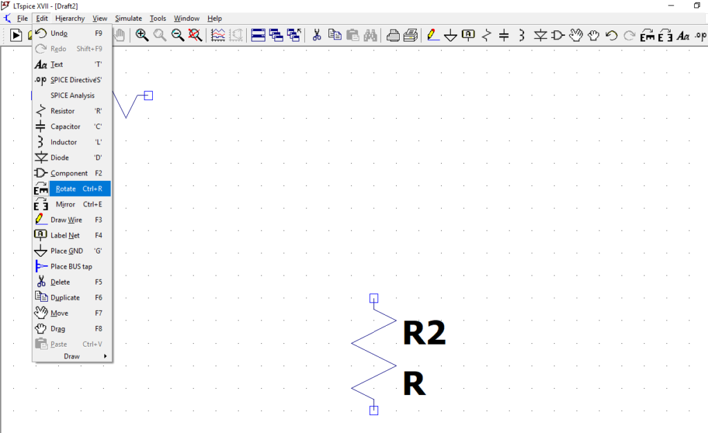
Figure 4: Rotate Function
Connect the resistors using wire, click on the wire icon now click on to the node of resistor R1 and drag the wire to the resistor R2.
![]()
Place the ground, click on to the following symbol, and position as shown in the fig below.
![]()
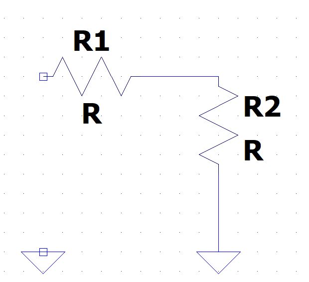
Figure 5: Ground connection
Now place the voltage source in the given circuit, click on to the component symbol , and you would get the select component symbol popup from the list select the voltage source.
![]()
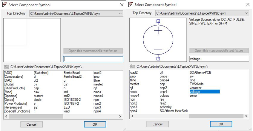
Figure 6: Select component
Place the voltage symbol from the schematic and then press escape to come out of edit mode. Connect the voltage Vin to resistor R1 and ground through a wire. The circuit is complete, and now define the value of the components. Right-click on resistor R1, the following pop-up appears on the screen. Enter the value of resistance as 1k, similarly enter the value for resistor R2.
In case if the name of the component has to be changed, right-click on the component in this example, let us change the voltage as Vin and set the voltage value to 1v.
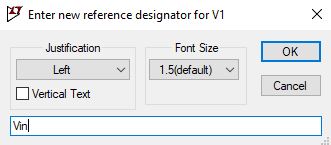
Figure 7: Naming component
To determine the operating point for the voltage divider circuit, we need to run the simulation. User must suggest LTspice what kind of simulation they would like to perform. Go to edit and select SPICE Directive’S’ and then type .op for the operating point.
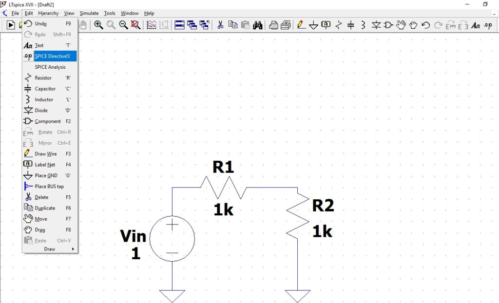
Figure 8: Spice Directive’S’
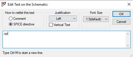
Figure 9: Circuit operating point
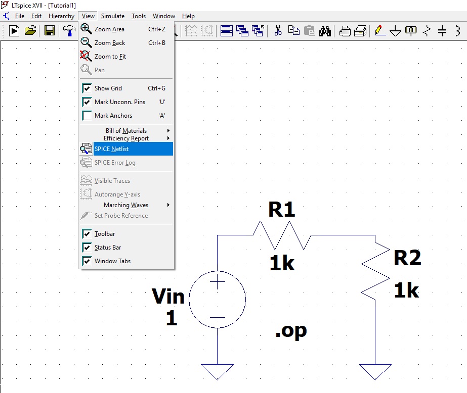
Figure 10: Complete circuit
Save the schematic, before running the simulation if you would like to view the spice netlist. Click on view–>select spice netlist.
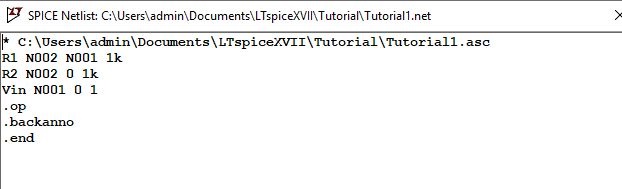
Figure 11: Spice netlist
To run the simulation, click on the following icon
![]()
The simulated results below shows our operating point across the various nodes. Users can click on the spice error log, to understand how long the simulation has taken to complete.
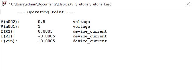
Figure 12: Simulation analysis
We can also define our node name in the LTspice, to do this click on the label net.
![]()
In this example, enter the net name as Vin, select the point to place this label net. Click on the spice netlist, you can observe the following changes in the netlist.
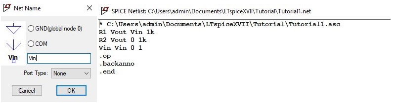
Figure 13: Spice Netlist
The tutorial on simulation of simple voltage divider circuit is complete using LTspice.