The 555 timer, one of the most frequently used integrated circuits by design engineers for novel circuit designs.
The 555 timer IC got the name due to the three 5 kilo-ohms resistors used in the voltage divider network. They find potential use in numerous applications such as time delays and oscillators.
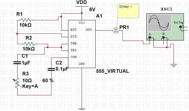
In this circuit design tutorial, a 555 timer to be used for frequency variation circuit application. In a traditional circuit design to keep the duty factor constant, and change the frequency continuously, can be achieved through a variable capacitor.
If we change the value of resistors, the frequency varies at the cost of sacrificing the duty factor.
To overcome this, we can use a variable resistor. This tutorial will help, how to simulate the circuit shown below using the NI multisim tool.
The table below depicts various frequencies for different values of the variable resistor.
| Variable Resistor VR(Ω) | Frequency(Hz) |
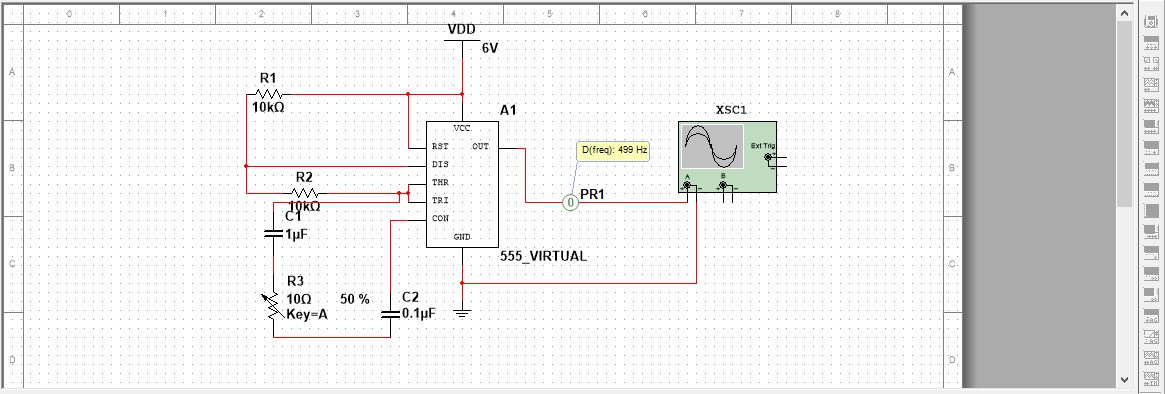
| 10 | 499 |
| 33 | 500 |
| 68 | 501 |
| 100 | 502 |
| 220 | 506 |
| 500 | 516 |
| 1000 | 534 |
Let us start the circuit design using the multisim tool.
Multisim is a suite of EDA tools that will assist design engineers in their circuit simulation and design flow.
The list of components used in this circuit design 555 IC, power source, resistors, capacitors, variable resistor, ground, and oscilloscope.
NI Multisim tutorial on frequency variation circuit using 555 timer
Start placing the components, click on place, then select components, we will get select a component pop-up.
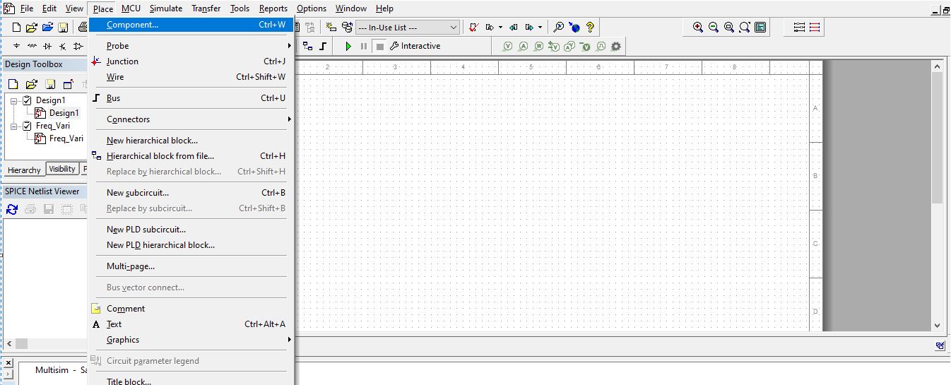
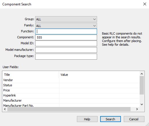
The design requires 555 IC for this design, click on search, a component search pop-up appears.
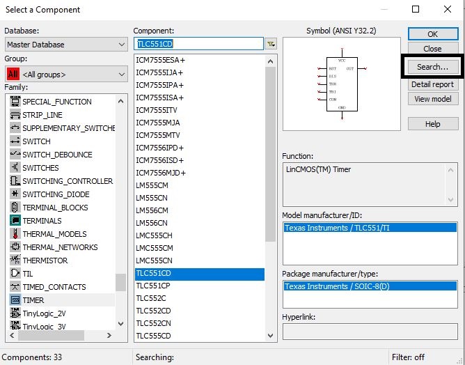
In component section type 555, click on search.
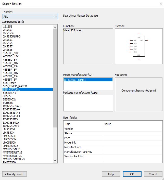
Search result pop-up box appears, select 555_virtual and click ok.
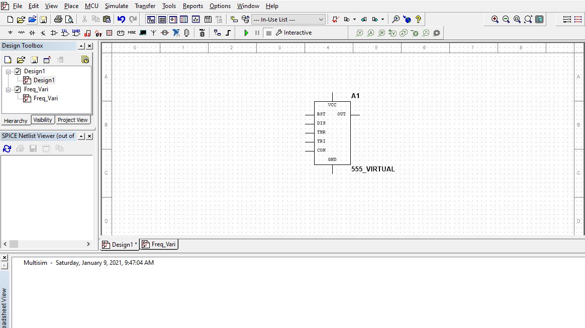
Drop the 555 timer on the schematic capture window. Next, we must place the power source, resistors, capacitors, and variable resistors.
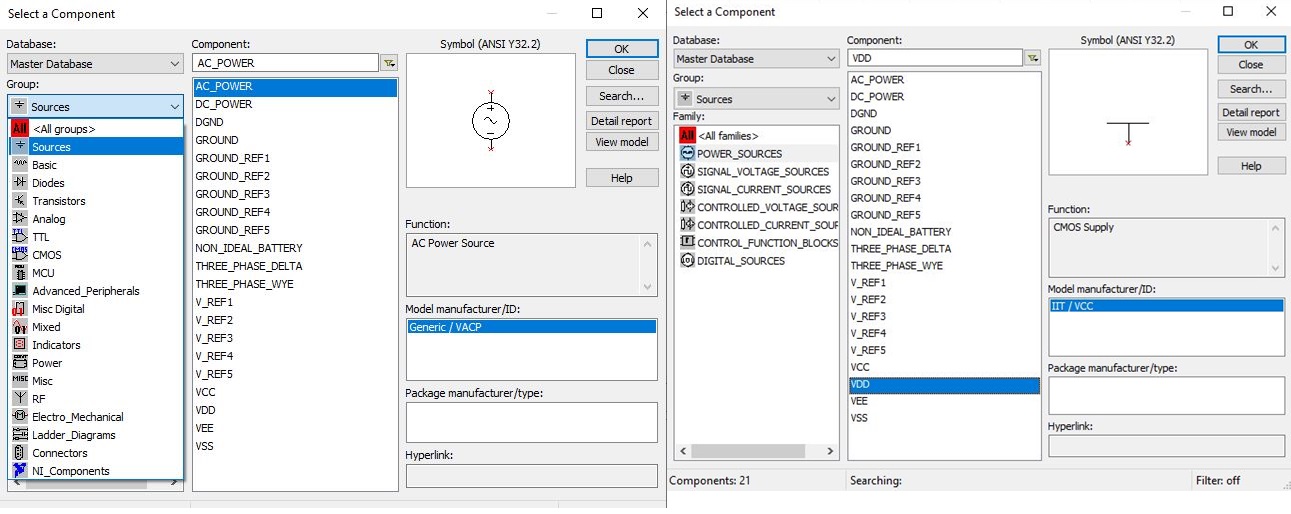
Click on place, select component, we will get select a component pop-up.
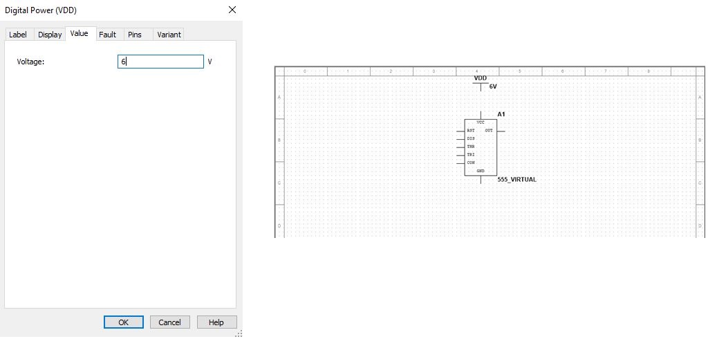
In group drag down and select sources, select power sources and component VDD.
Place the source VDD on the schematic capture, double click on VDD, and change the value to 6V.
Connect the power source to the Vcc pin, when the cursor is placed on Vdd, the cursor would change to a plus symbol. Click on that and drag the wire to the Vcc pin and click to complete the wire. Move the cursor towards the reset pin, click on the pin, and drag the wire towards the Vcc pin.
Click on place, select components, select a component pop-up appears. In group drag down, and select group as Basic–> Resistors and in component section 10k.
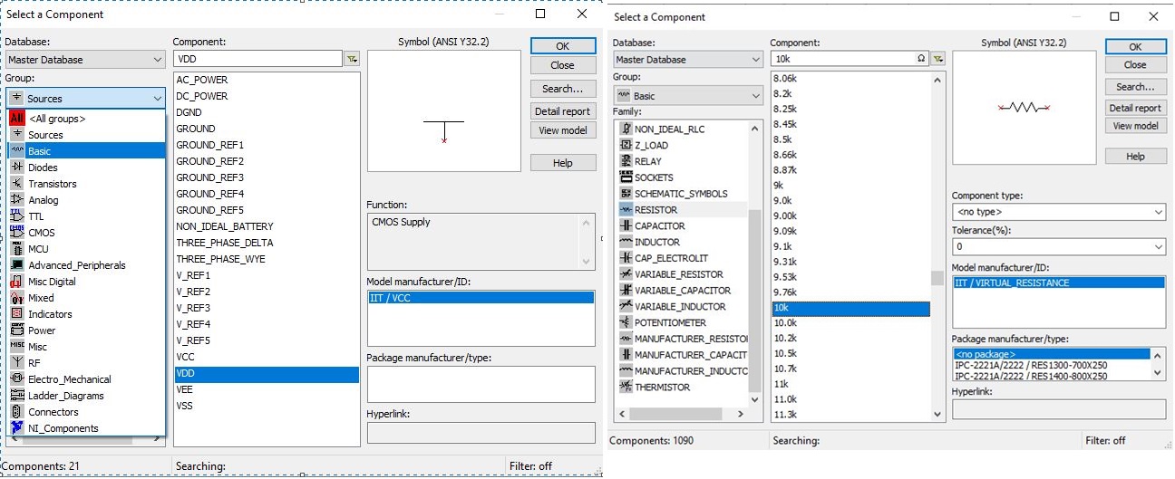
NI Multisim component selection
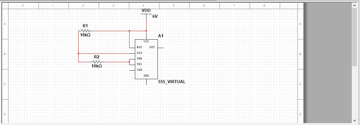
Place the 10k resistor, connect the resistor to the Vdd and RST wire. The other end of the resistor to the discharge pin. Connect the threshold pin of the 555 timer to the trigger pin. Click on place, select components, select a component pop-up appears.
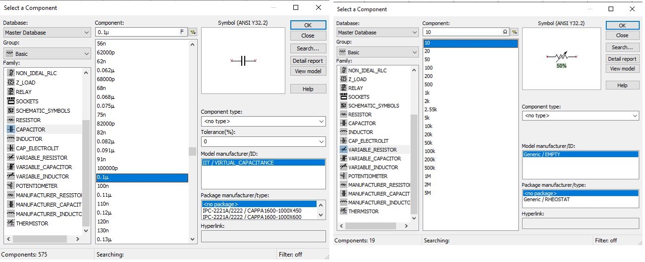
In group drag down, and select group as Basic–>Capacitors and in component section 1uF. Place the 1uF capacitor, on the schematic capture. Click on place, select components, select a component pop-up appears. In group drag down, select group as Basic–>Variable resistors and in component section 10 ohm.
Place the 10-ohm variable resistor, on the schematic capture. Connect the C1 terminal to the trigger pin and the threshold pin, the other end of the C1 terminal to the variable resistor R3.
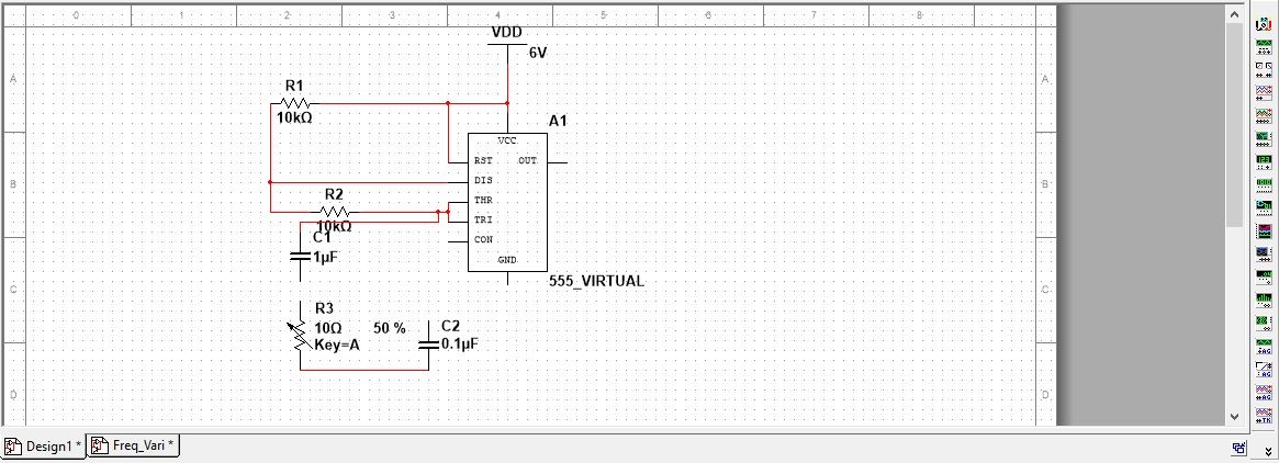
The other end of R3 is connected to the C2 and then to the control voltage pin of the 555 timer.
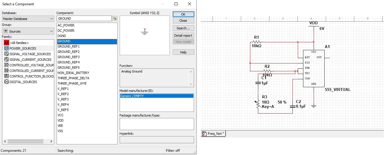
The ground terminal and the oscilloscope must be placed in the schematic capture to measure the frequency.
Click on place, select components, select a component pop-up appears. In group drag down, select group as sources–>Power sources and in component section ground.
Place the GND on the schematic capture, drag the wire from the GND pin to the ground terminal.
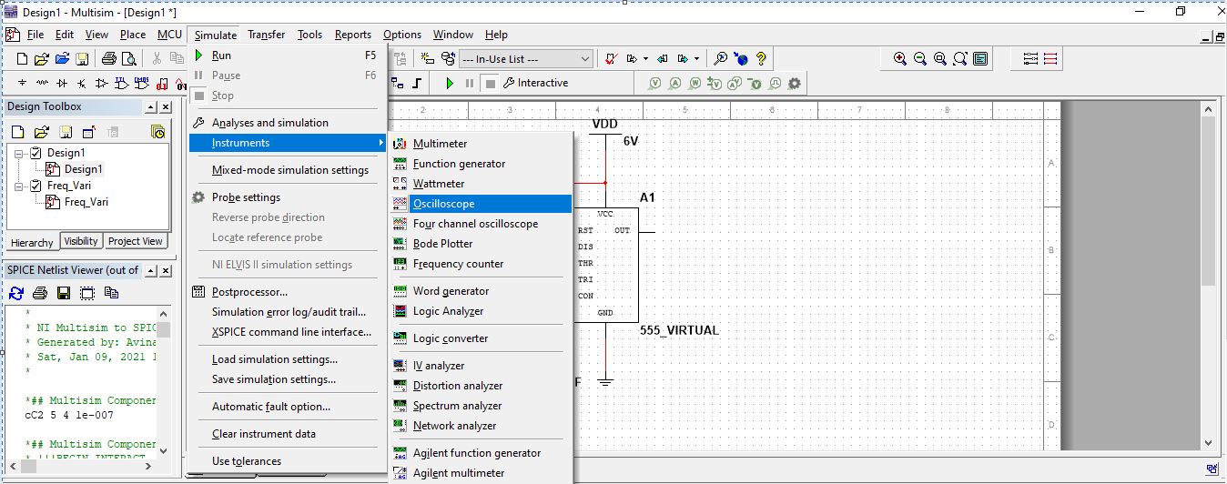
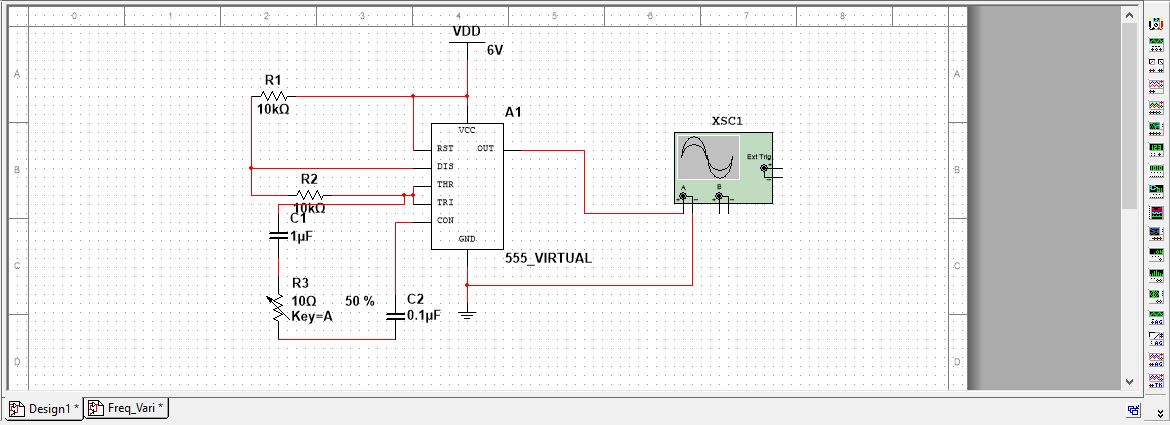
To measure the frequency from the output pin of the 555 timer, connect this to the oscilloscope. Click on simulate–>Instruments and select oscilloscope. Place the oscilloscope on the schematic capture, connect the output of 555 timer to the channel A terminal of oscilloscope and negative terminal of channel A to ground.
How to perform simulation on NI Multisim
To measure the frequency, we must place the digital probe. Select the digital probe and place it on the output wire.

To simulate this circuit, click on the run button. Observe the frequency value on the digital probe placed on the output wire.
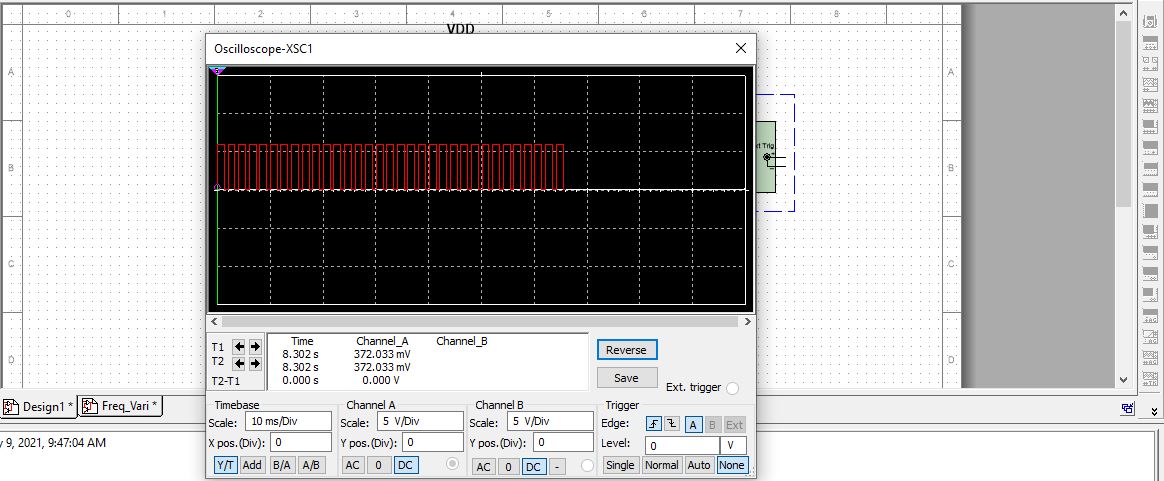
Double click on the oscilloscope to see the frequency waveform. When the variable resistor value changes, the frequency also changes.
End of tutorial.
You can also check the tutorial on circuit generator Youtube platform.
Disclaimer: The opinions expressed within this article are the personal opinions of the author. Circuit Generator is not responsible for the accuracy, completeness, or validity of any information on this article. Circuit generator does not assume any responsibility or liability for the same.