RF circuit technology has evolved a lot since the times of Guglielmo Marconi and Nikola tesla, both pioneers and visionaries who enabled radio communications. Their innovations empowered path-breaking innovations in RF applications ranging from mobile phones to radar. During the early 1980, RF circuit technology found its use typically for defense-related applications. Today many consumer related wireless applications have adopted RF circuit.
According to Statista, the number of mobile phones shipped globally set to reach 17.72 billion. Adoption of RF circuit created a wealth of business opportunities but also devised new design challenges for RF engineers.
Some of the considerable design challenges include multiband subsystems and parasitic elements that influence the circuit performance. Most of the organization develop their high-frequency design tools to address their design challenge needs. Texas Instruments developed the first CAD tool for microwave circuit CAIN-01 in 1971. As time progressed, many EDA companies have access to RF microwave products that aid design engineers to validate the design.
What makes an RF circuit system?
When the bits and pieces of components such as resistors, capacitors, and inductors combination, make up a radio frequency circuit. Wire does form a crucial element in the RF circuit. The behavior of wire depends on the size, length, and diameter. When we consider wire in an RF circuit, engineers must consider many factors such as skin effect, straight wire inductors, and the components equivalent circuit.
Let us understand some of the factors essential for designing the RF circuit system.
The first-factor design engineers must ponder about what is the skin effect?
At low frequencies, a conductor utilizes the entire cross-sectional area as a transport medium for charge carriers. When the frequency increases, the magnetic field increases at the center of conductors, thus decreasing the current density at the center of the conductor.
Any current-carrying conductor, there exists a magnetic field. An alternating current through the conductor produces a voltage on the wire, which opposes any change in current flow, known as self-inductance. Inductance of a wire depends on length and diameter, calculated as shown below.
L= 0.0021[2.3 log (4l/d)-0.75] uH
L=inductance in uH
l=length of wire in cm
d=diameter of wire in cm
Inductance becomes a crucial factor since all conductors at radio frequencies tend to exhibit properties of inductance.
For an RF circuit system, the resistance of the circuit would impact the RF spectrum.
Resistors used in the circuit, in most instances such as in transistor biasing network, the resistor perform its DC circuit function but disrupt the circuit’s RF operating point.
Equivalent circuit of the resistor at radio frequencies
The figure below depicts the equivalent circuit of the resistor at radio frequencies.
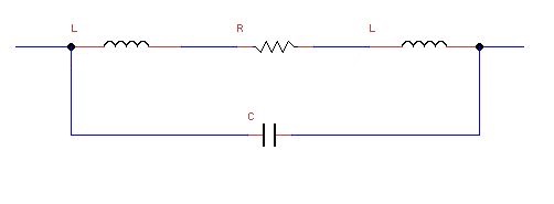
L-lead inductance
C-parasitic capacitance
The value of lead inductance and parasitic capacitance depends on the structure of the resistor. Resistors made up of carbon composition are poor high-frequency performers. Carbon-based granules present in resistors cause the parasitic capacitor.
Wire wound resistors exhibit problems at radio frequencies it exhibits varying impedance over numerous frequencies, and impedance of the wire-wound resistor increases as the frequency increases. At the particular frequency, the inductance will resonate with shunt capacitance leading to an impedance peak. Any further increase in the frequency will decrease the resistors impedance.
Another crucial component used in an RF circuit design, the capacitor, is a two-terminal device, which consists of two conducting surfaces separated by insulating dielectric material. The property of a capacitor is to store energy when a potential difference exists between conductors.
C=Q/V
Q= Charge in coulombs
V= voltage in volts
C= capacitance in farads
Equivalent circuit of the capacitor at radio frequencies
In a capacitor equivalent circuit, the phase angle (Ф) will be small due to total series resistance.
Power factor (PF) = cos (Ф)
An insulator resistance defined as the measure of DC-current that passes through the dielectric of the capacitor, with voltage applied.
The effective series resistance of the capacitance equivalent circuit is the combination of insulation resistance and heat dissipation loss.
ESR= (PF/wC)*(1×10^6)
Dissipation factor= AC resistance/Reactance of capacitor
DF= ESR/Xc*100%
The quality factor of a capacitor is the reciprocal of the dissipation factor.
Q=1/DF=Xc/ESR
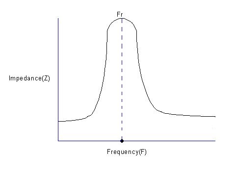
The graph below depicts the impedance characteristics of an ideal capacitor plotted against a real-world capacitor.
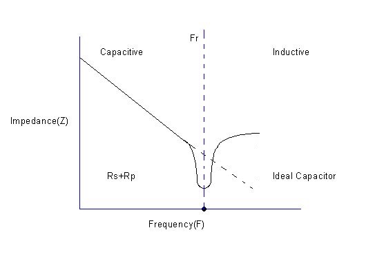
As the frequency of operation increases, at Fr, the inductance becomes series resonant with the capacitor. Above Fr, the capacitor acts like an inductor.
Equivalent circuit of inductor at RF frequencies
Inductor used in an RF circuit system a wire-wound. Inductor increase the magnetic flux linkage between turns of the coil. Inductors find extensive use in RF design in phase shift, delay network, filters, and resonant circuit.
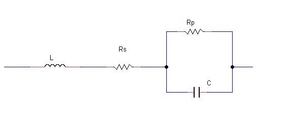
The depiction of an equivalent circuit of inductor at RF frequencies shown below.

When two conductors at close proximity, but separated by a dielectric, and the voltage difference between them gives rise to the property of a capacitor. If a wire resistor exists, then there will be a voltage drop between winding and small capacitors formed, known as distributed capacitance.
The graph below depicts the effect of cd upon the reactance of an inductor.
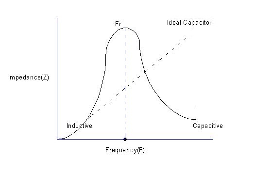
The inductor’s reactance parallels that of an ideal inductor, as the frequency increases at the inductor parallel resonant frequency (Fr).
Above Fr, the reactance of the inductor begins to decrease with frequency, and the inductor act as a capacitor.
Conclusion
Passive components play a crucial role in RF circuits.
Design engineers must select the components and material accordingly such that it meets all the design requirements. Also critical to understand that it is impossible to have ideal inductors, capacitors, or resistors and eliminate the unwanted parasitic components.
Disclaimer: The opinions expressed within this article are the personal opinions of the author. Circuit Generator is not responsible for the accuracy, completeness, or validity of any information on this article. Circuit generator does not assume any responsibility or liability for the same.
Great work