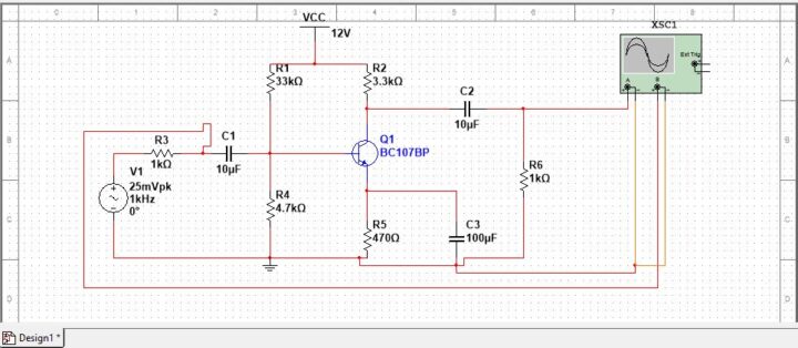
In this tutorial, we will simulate the common emitter amplifier using multisim tool. The objective is to determine the gain and the bandwidth of a CE amplifier based on the frequency response curve. Common emitter amplifier also known as voltage divider biasing or self-biasing. Common emitter amplifier uses two resistors, which act as a potential divider network, used in the design of bipolar transistor amplifier circuits.
The resistor present at the collector circuit of the common emitter amplifier, in which current flows through the resistor. The resistor value impacts the amplifier quiescent operating point, Q point. The impact is such that the output voltage lies halfway along the transistor load line. The capacitor present in the common emitter amplifier circuit act as coupling capacitors to separate AC signals from DC biasing voltage. Thus the capacitors ensure that only AC signals are passed and block the DC component.
The bypass capacitor short circuits the emitter resistor at high-frequency signal. The small internal resistance act as the load increasing voltage gain to its maximum. In a single-stage common emitter amplifier, an increase in base voltage causes a decrease in output voltage and vice-versa. The output signal during the simulation is 180 degrees out of phase with the input signal.
How to simulate common emitter amplifier using multisim tool?
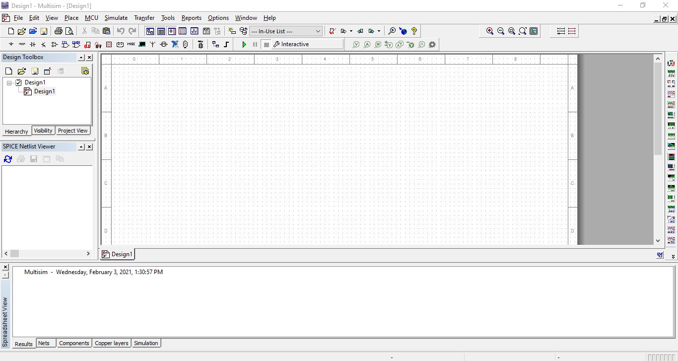
Start multisim tool, for the common emitter amplifier circuit we require the following components.
Components include resistors, capacitors, transistors, voltage source, power source, and ground connection for designing this circuit.
Click on the place or place transistor icon, then select a component pop-up that appears.
![]()
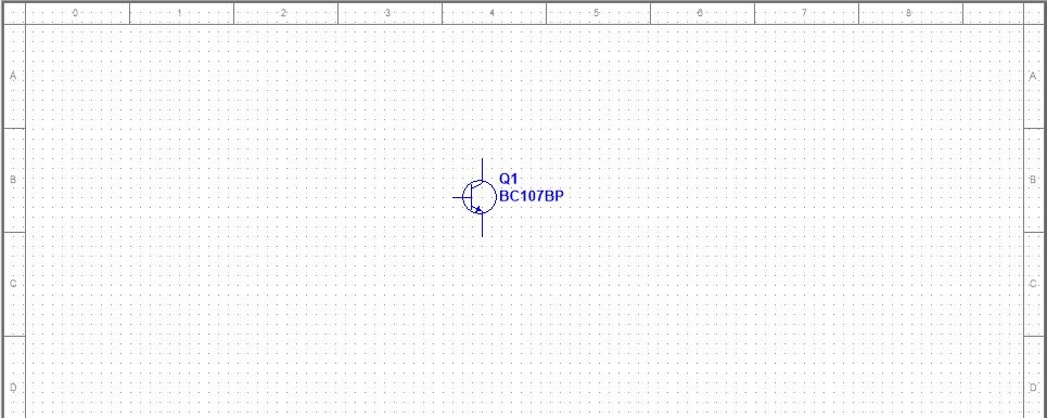
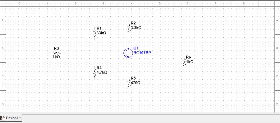
In the component section, search for BC107BP and select this NPN general-purpose transistor and place this on the design window. 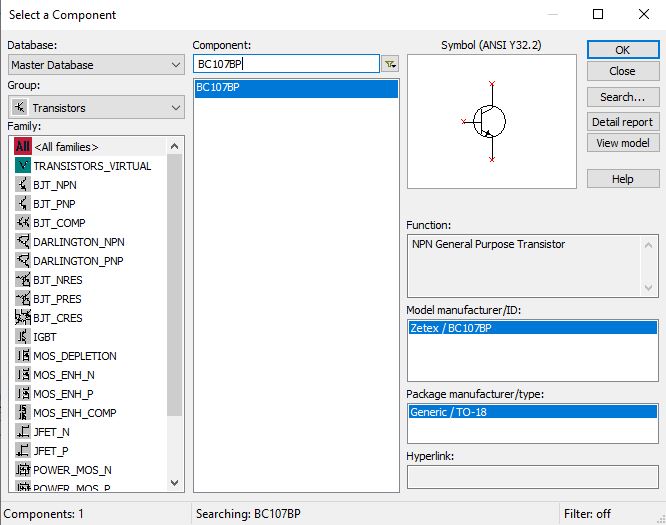
Now click on place, then select component, in group section select basic and then select resistor. In this multisim tutorial, we require the following resistor value 33k, 3.3k 1k, 47k,0.47k ohm for the circuit design.
Place all the resistors as shown in the figure below on the multisim design window.
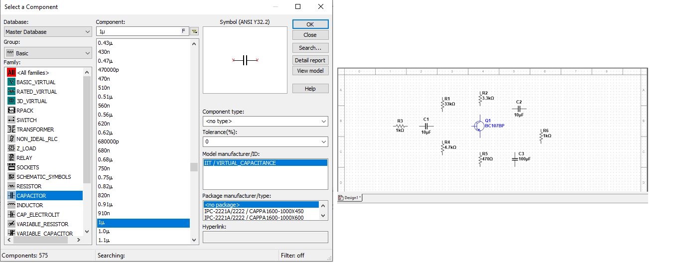
The next step in this multisim tutorial to place the capacitors of the following values 10uf and 100uf on the multisim design window.
Click on place, select component, in group section select basic then select the capacitors.
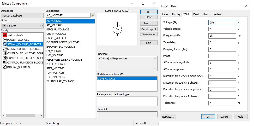
We require input source and TTL supply, click on place, and select component, then select the group as source and Vcc (TTL supply) click ok.
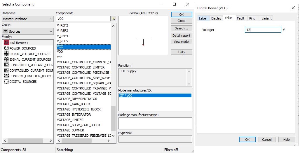
Place the Vcc on the multisim design window and double click on Vcc to change the value to 12V. Double click on the AC power source, and change the voltage to 25mV and frequency to 1khz.
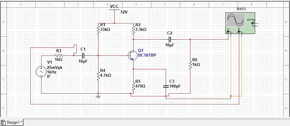
Connect all the components with proper wiring and also ensure that nodes are formed at the interconnection points.
In this tutorial, we must place the ground and the two-channel oscilloscope to simulate the input and output of the circuit.
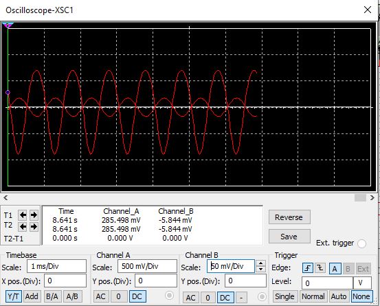
Now to determine the gain of the common emitter amplifier, click on the run button. Double click on oscilloscope.
Common emitter amplifier multisim output simulation
Make the following changes on Time-base, channel A, and channel B.
Select AC sweep and enter the following parameter.
Start Frequency- 1Hz
Stop Frequency- 10MHz
Sweep type: Decade
Number of points per decade: 25
Vertical sale: Decibel
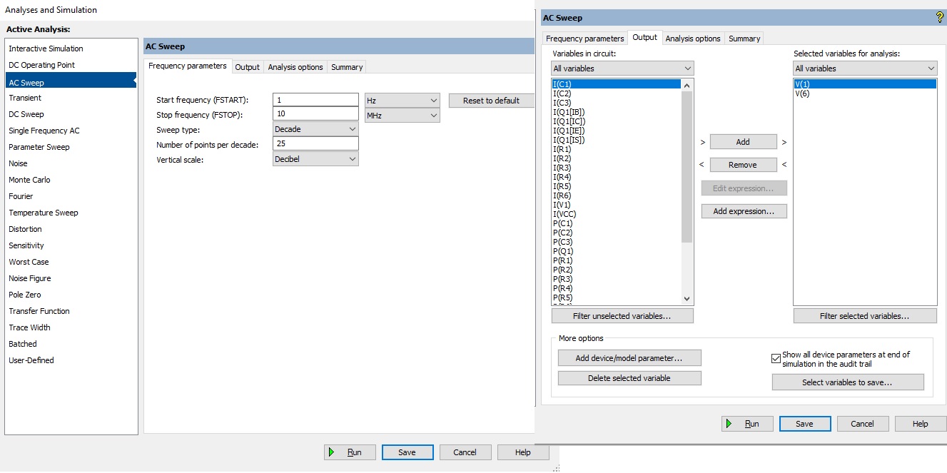
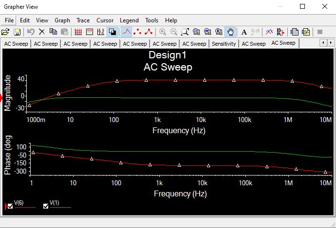
In the output, add variable V(1) and V(6), run the simulation.
You can see the bandwidth of a common emitter amplifier based on the frequency response curve.
End of tutorial