In this tutorial, we will design a voltage divider circuit and perform the circuit simulation using the KiCad tool.
This tutorial will cover the circuit design on Eeschema, and we will perform the circuit simulation using the KiCad tool. To start with, click on the file, New>Project.
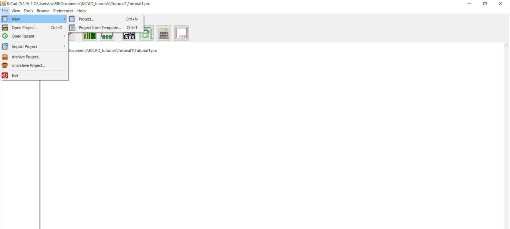
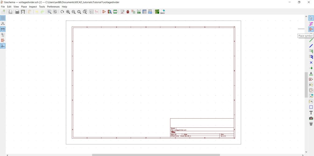
Save this project as a Voltage divider, and next double click on the schematic layout editor. We will start the circuit design on the Eeschema, to begin with, click on the place symbol icon.
How to choose symbol in KiCad?
Click the cursor on the schematic layout editor, and this will load the global library component list present in the KiCad. For this circuit simulation using the KiCad tool, we require the following components resistor, voltage source, and ground connection. In the filter section, type Pspice and then select the resistor symbol for the simulation and click OK. To rotate the resistor symbol, double click on the resistor. Define the reference as R1 and the value as 1k and select orientation as +90.
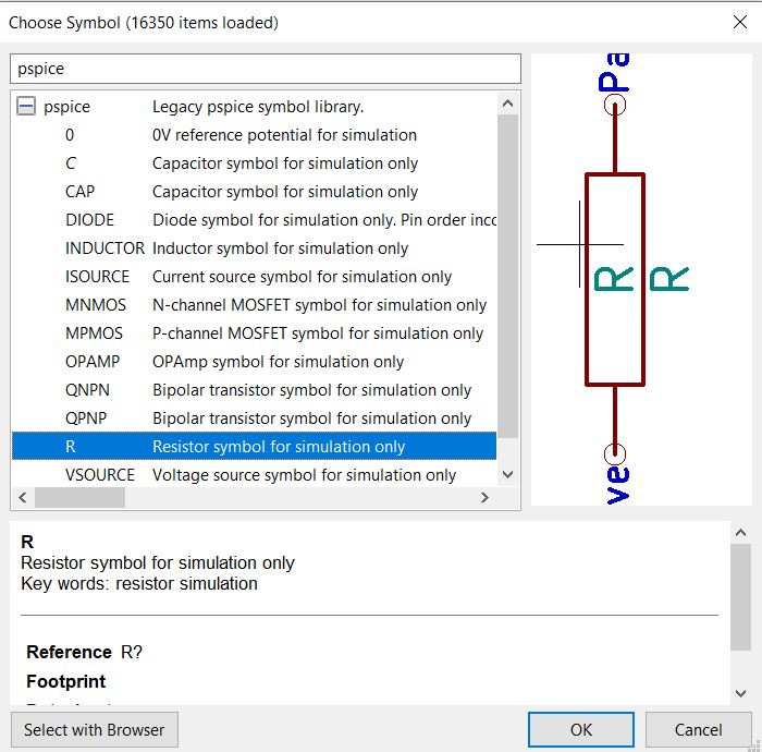
Click on the place symbol and click on the schematic editor window, and chose the symbol R.
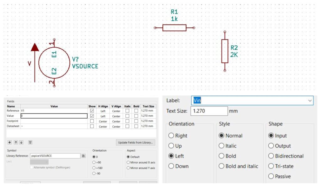
Place the resistor R2 on the Eeschema and double click on the resistor. Define the reference as R2 and the value as 2k, then click OK.
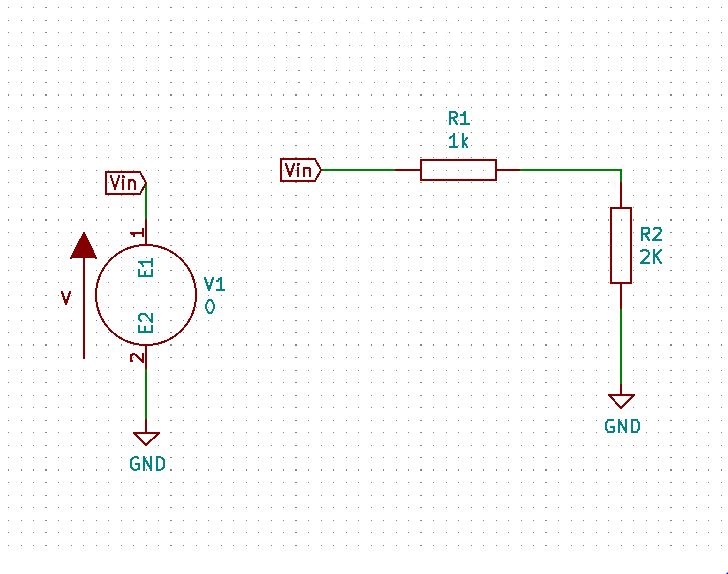
We need to add the power source that SPICE understands, place a new VSOURCE voltage source component in the schematic. Wire this as a label, Vin, to the positive side and GND power port to the negative side of the VSOURCE component.
Double click on the VSOURCE component and change the reference as V1 and the value as 0. Connect the resistor R1 and R2 and the input Vin using the wire as shown in the schematic below.
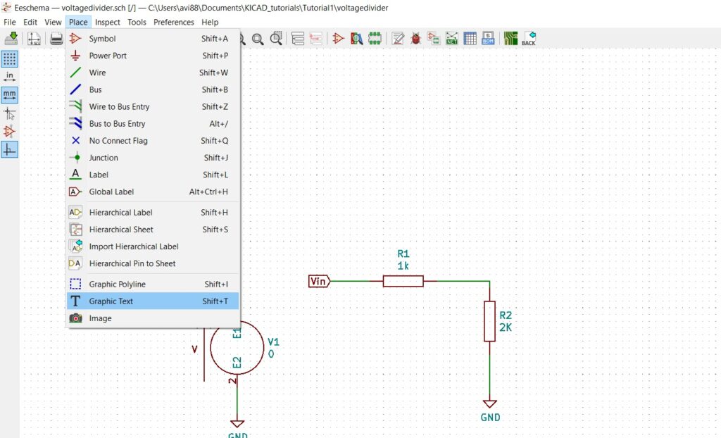
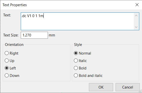
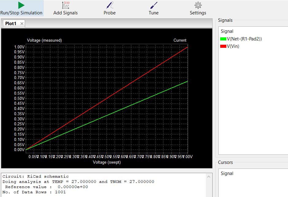
Now the voltage divider circuit is complete, perform the circuit simulation using the KiCad tool to plot the DC transfer characteristics and the transient analysis. To perform the DC analysis, we tell the SPICE(ngspice) what we want to simulate. The best way to execute this is by placing the control statements directly in the Eeschema. Select Place>Graphic text from the main menu, enter the control statement and click OK.
How to perform the Spice simulation in KiCad?
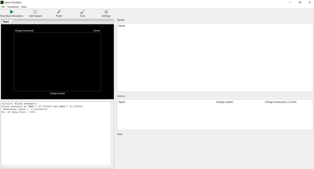
To perform the simulation, click on tools and select the simulator. Click on the Run/Stop button, the following plot screen will appear.
Click on the probe, place the probe on Vin, and between the resistor R1 and R2. You can check the SPICE simulator for the following DC transfer characteristics.
To perform a transient analysis, we must change the VSOURCE voltage, double click on VSOURCE, click on edit spice model a pop-up of SPICE model editor opens.
Select the source as sinusoidal, enter the following values.
| Value of DC offset | 0 |
| Amplitude | 1 V |
| Frequency | 1 Meg |
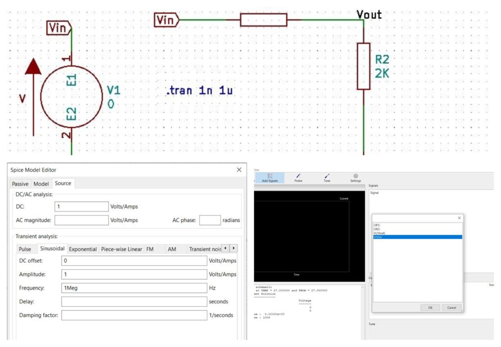
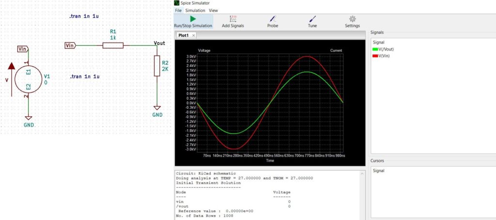
Edit the graphic text to .tran 1n 1u and click on tools>simulator. Click on the run button and next click on add signals. Select the V(Vin) and V(/vout). The transient analysis of the circuit is plotted on the waveform viewer on the left.
End of circuit simulation tutorial.