In this modelsim tutorial we will simulate the Inverter using modelsim tool. Before going into this tutorial we must answer one of the basic questions.
What is hardware description language?
Hardware description language is a language used to describe a digital system. In modelsim the basic simulation flow is shown below
- Create a working library
- Compile the design file
- Load and run the simulation
- Debug the results
In modelsim all the designs are compiled into a library, so the first step is to create the work library.
Creating work library modelsim tutorial
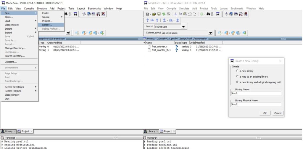
Go to file, select New and click on library. Create a new library pop-up box appears, select a new library and a logical mapping to it. Define the library name as work and click ok. Library work is created.
Compile the design file modelsim tutorial
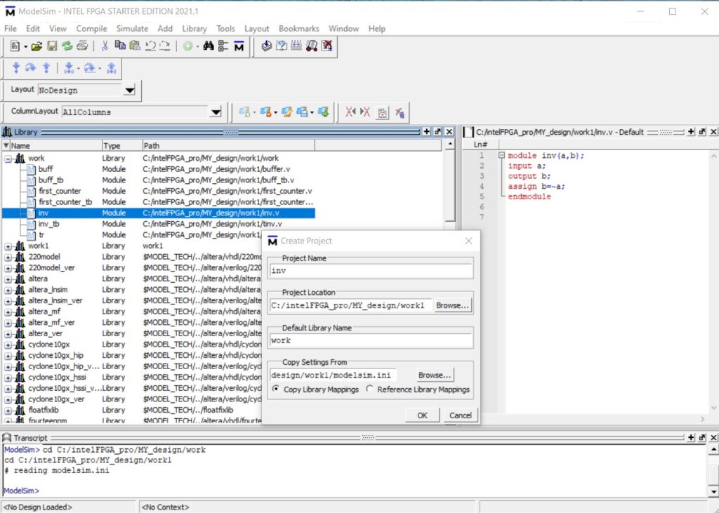
Now we must create a new project Inverter, type the project name as Inverter and then select the default library name work, select copy library mapping and click ok.
A blank project window appears, right click and select add to project and then select new file.
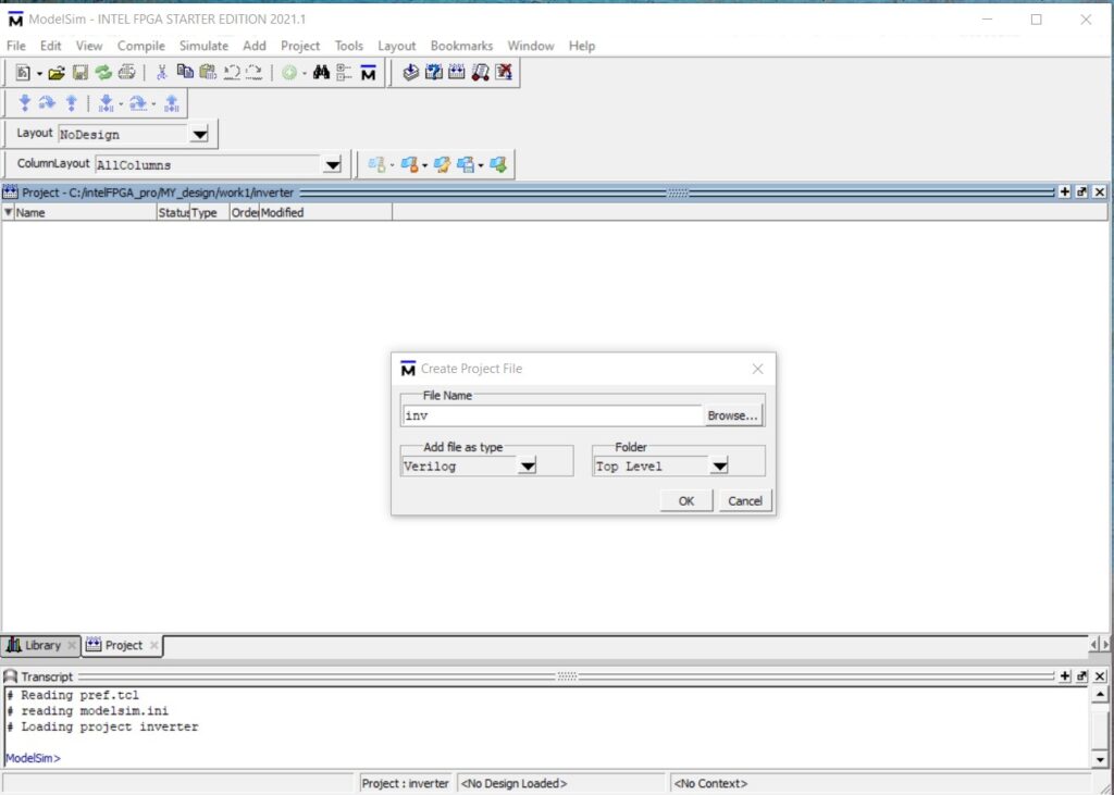
Create project file pop-up appears type the file name as inv and select add file type as verilog and click ok.
Double click on inv.v, on the right hand side the programming window appears. The inverter program for reference below.
Modelsim tutorial- Inverter Verilog Code
module inv(a,b);
input a;
output b;
assign b=~a;
endmodule
The Verilog module has a declaration and a body. In the declaration name, input and output of the module is defined. The body shows the relationship between the input and outputs.
The name of the module is inv which is user selected and case sensitive in verilog. The name of the module should start with an alphabetical letter and can include special character underscore. The declaration of the module starts with a predefined word module, followed by user selected name.
We must define the input and the output for the inverter as shown in the image above.
The signal assignment statements assign b=~a, representing that the not or the inverter operation, defined as a logical operator. The predefined word endmodule terminates the module.
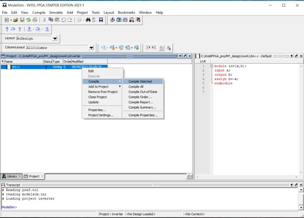
Right click on the question mark and select compile and then select compile selected.At the bottom of transcript we will get compile of inv.v was successful.
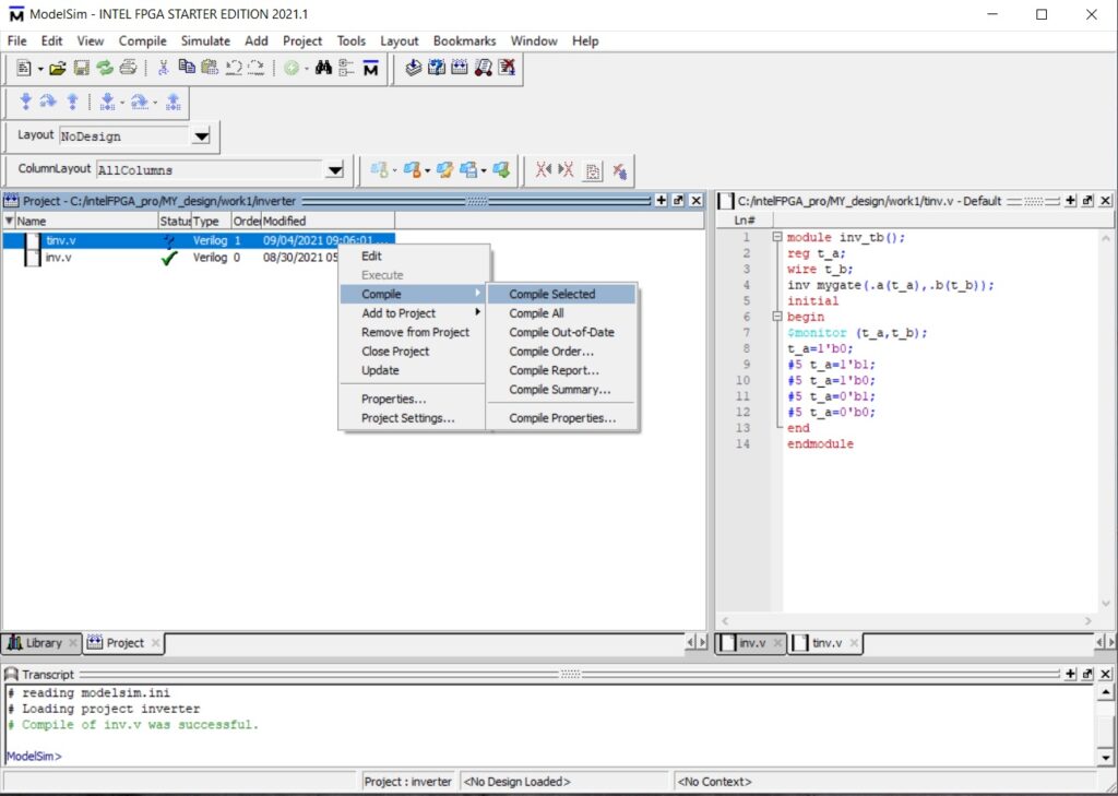
Next step in this modelsim tutorial, we must create a testbench for the inverter. Right click and select add to project and then select new file.
Create project file pop-up appears type the file name as tinv and select add file type as verilog and click ok.
Double click on tinv.v, on the right hand side the programming window appears.
Modelsim tutorial- Testbench code
module inv_tb();
reg t_a;
wire t_b;
inv mygate(.a(t_a),.b(t_b));
initial
begin
$monitor (t_a,t_b);
t_a=1’b0;
#5 t_a=1’b1;
#5 t_a=1’b0;
#5 t_a=0’b1;
#5 t_a=0’b0;
end
endmodule
The function of testbench is to apply stimulus to the design and report the output in a readable format. The testbench starts with module definition and then DUT(design under test). Input to DUT is reg and output declared as wire.
To display the value of a signal we must define the $monitor syntax, this displays value every time when one of its parameters changes.
The syntax #5 defines the time unit necessary for the simulator to understand the scale directive. Similarly compile the testbench.
Simulation and Debugging the result
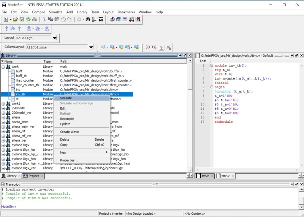
Next in this modelsim tutorial we must simulate the inverter waveform. Go back to the work library, click on plus and you can see both inv.v and tinv.v module. Now right click on tinv.v and click on simulate.
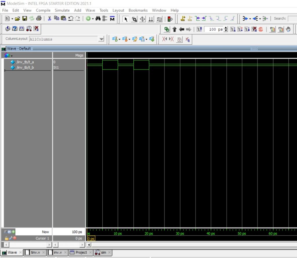
The sim window appears, right click on inv_tb and click on add wave.
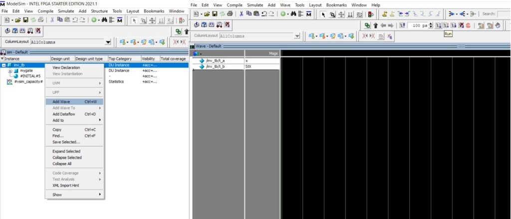
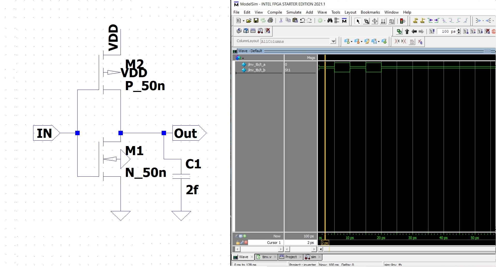
Hover to the waveform window and click on the run button.
The inverter functional characteristics are verified through waveform output from the simulator.
Please click on the link below for the video tutorial.
End of tutorial.